Cable Drum Trailer the cable drum trailer is used to transport the cable drum. Figure 4-4 shows a typical thermal model of the heat losses and thermal resistances.

Electrical Cable Trench Design Detail Autocad Dwg Plan N Design
From outdoor Switchyard or from the Dead End Tower of a Transmission Line within the Switchgear or Control building.

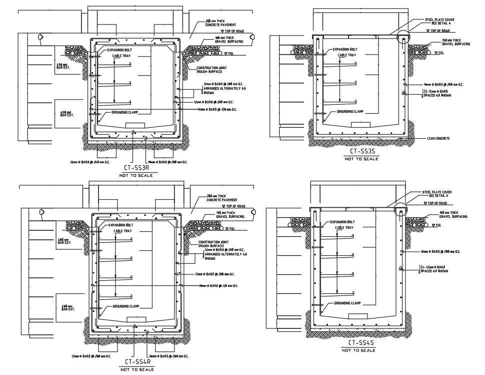
. RCC Design Of Cable Trench Excel Sheet. Slope floors towards the piping side of the tunnel to minimize water on walking surfaces. Autocad drawing of Electrical Cable Trench.
Electrical Cable Trench. Jan 28 2020 - Autocad drawing of Electrical Cable Trench Details showing construction detail through a detailed section. Maintain uniform tunnel slope between manholes.
Make a sand bed or fine riddled soil bed as per the measurements given in the drawing. It is the constructors responsibility to confirm before construction that the details on this drawing are correct as per SUB-03-017. Provide embedded inserts and plates for piping and cable tray supports.
An earthing drawing based on one of the standard layouts. If an internal isolated Electrical Room is required the customer must install a secondary splice can at the outer wall nearest the transformer. This section displays drawings for smoke detector CAD details electrical distribution board drawing electrical wiring routing detail AutoCAD electrical symbol blocks CAD electrical panel drawing along with electrical layouts for DG Rooms conference rooms kitchen bedroom storeroom food courts and offices.
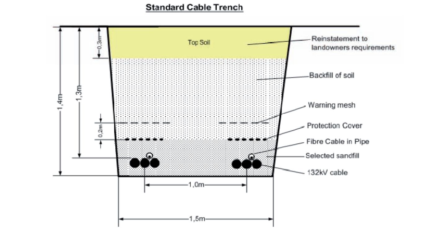
For multi-core cable applications multi-stranded conductors must be used. The cable component materials and the surrounding environment cause the cable temperature to rise above the surrounding ambient temperature. The cables are submerged underground via the trench and are then covered by a layer of earth bitumen or concrete.
From outdoor Switchyard or from the Dead End Tower of a Transmission Line within the Switchgear or Control building. RCC design of cable trench excel sheet allow to to analysis and design the Trench. Download RCC Design Of Cable Trench Excel Sheet Free.
3 x Red Cable Marker Strips 400mm Wide x 25mm Thick Ducts Laid in CBGM A 125mm Outer Diamter HDPE B 200mm Outer Diameter HDPE B B B B B B B B B B B B 1This drawing is for development purposes. Design Drawings and Profiles 27 132kV Underground Cable Work No. Cost to be incidental to sewer installation tongue and groove cross section exaggerated bell and spigot cross section exaggerated dry trench wet trench dry trench wet trench revised 022714 by nw jcitydwgcivil 3d drawingsdtlcity sddstrench section detailpdf trench section typical scale 1 1.
Refer to drawing below. This drawing shows the route of the Power Control cables coming to Switchgear Control Relay panels etc. After taking trench keep clean the trench for the following steps.
31 75 00 - Shaft Construction. The Indoor Cable Trench Layout drawing is the one of the most important drawing of the EHV Substations. As part of the 50 Front End Engineering Design the preliminary cable layout design was developed based on an assessment of multiple route options driven by the shore crossing route for the export cable.
The cable route must cross or go around the breakwater and then cross the Harbor to connect into the project substation. F Substation Standards Cable Trench Grounding 17. The earthing construction manual is not a substitute for the earthing design manual which covers the.
Installed under an LV main cable in the cable trench. G Substation Standards Pipe-Bus Grounding Plan 18. Using the available information.
For a two-trench design there will be a separation of approximately 3m between the two trenches and 7m between the two cables Figure. 4213 AC and DC cables must be 061 kV rated. The cable is then pulled through the trench with the draw roller acting as an initial guide for the cable.
Design utility tunnels and trenches in accordance with ACI standards and as shown in the tunnel and trench sections. ElectraNets Standard Drawing 510 STD257-001 which covers all indoor and outdoor applications. Cable trenching is a method of laying cables into the ground by digging trenches.
K Substation Standards Switch Operating and Equipment Platforms Electrical Design and Details 20. Cable rating maximum allowable load current is. Final cable trench details will change.
31 66 16 - Special Foundation Walls. The onshore cables trench will be approximately 13m deep and 45m wide with an approximate distance of 1m between the two HVDC cables if both cables are within a single trench Drawing NCGEN-NCT-Z-XE-0003-01. In addition the trailer is also used to stabilise the cable drum.
31 70 00 - Tunneling and Mining. When the cable is pulled through the open trench the draw off roller leads the cable straight from the drum into the trench. HDD DRILLING RIG PROPOSED DIRECTIONAL DRILL ROUTE PROPOSED OPEN CUT TRENCH ROUTE ROAD LEVEL RIVERSTREAM BED LEVEL GROUND LEVEL 1All dimensions are in metre unless otherwise stated.
4214 Cable conductors must be copper. This drawing shows how to lay a Low Tension LT power cable single core direct buried method. Lay the cable in the middle of the trench.
109 CAD Drawings for Category. This drawing shows the route of the Power Control cables coming to Switchgear Control Relay panels etc. 31 66 00 - Special Foundations.
Acceptance testing cable cable installation cable selection communication cable. 6 rows Engineering or Building Services. Design Assistance-we will be glad to discuss your requirements and help you with design ideas and recommend the optimum trench for your project.
Provide sand bed on top of the cable. This drawing is to be read in conjunction with document SUB-03-017 General Specification for the Civil Engineering and Building Design and Construction of Secondary Substations. 31 23 1613 - Trenching.
CABLE TRENCH INSTALLATION GUIDE GI0011U NOTES. The design and delivery of the project is a simple process and our Project Managers will guide and support you all the way. 4215 Power cables are classified for either indoor or outdoor application.
The Indoor Cable Trench Layout drawing is the one of the most important drawing of the EHV Substations. NVE cable trench is not approved for installation inside a building to serve an internal isolated Electrical Room. The design installation and protection of wire and cable systems in substations are covered in this guide with the objective of minimizing cable failures and their consequences.
2Cable trench details are based on simulations in CYMCAP for provided typical cables. D Substation Standards Lighting Fixture Pole and Bracket Mounting 19.

Electricveda Com Typical Cable Laying Details For Direct Buried Low Tension Cables

Rcc Cable Trench Details Dwg Cad Blocks Free

Outdoor Cable Trench Layout Of Ehv Substations In Newtown Kolkata Satcon Id 21609613448
Cable Trenches Layout Design Wind Farms Constructionwind Farms Construction
Autocadfiles Autocad 2d Dwg Drawing File Has The Plan And Layout Of Cable Trench Cable Trenching Is A Method Of Laying Cables Into The Ground By Digging Trenches The Cables Are
2d Autocad Dwg Drawing File Has The Foundation Details Of Cable Trench Download The Dwg File Cadbull

Outdoor Cable Trench Layout Of Ehv Substations In Newtown Kolkata Satcon Id 21609613448

Electrical Cable Trench Design Detail Electrical Layout Electrical Cables Electricity
0 comments
Post a Comment